
Article Summary:
A poor tube end can undermine an otherwise correct fitting assembly. This guide explains how to cut, deburr, clean and inspect hydraulic tube before it moves to bending, forming or cutting ring pre-assembly.
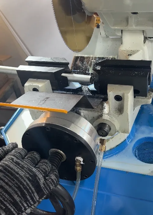
A fitting cannot correct a poor tube end. If the face is angled, the tube may not reach the assembly stop evenly. If a burr remains inside, it can hold chips and disturb cleanliness. If the outside edge is rolled, scratched or over-chamfered, the cutting ring may not engage the surface as intended.
The target is simple to describe: a square, round, burr-free and clean end that matches the fitting manufacturer's dimensional limits. Producing it consistently takes more than a quick pass with a file.
Use the fitting instructions as the acceptance standard
ISO 8434-1:2018 defines general and dimensional requirements for 24 degree cone connectors within its scope, but it is not a universal shop setup sheet. Cutting method, maximum angular deviation, chamfer and support-sleeve requirements can vary by connection system.
One published example is Parker's EO tube assembly guide . For the products covered by that guide, Parker specifies a square cut within plus or minus 1 degree, removal of internal and external burrs, and a maximum 0.3 mm by 45 degree chamfer. It also warns against using pipe cutters for those connections. Treat these as Parker requirements, not default values for every fitting on the market.
Before production, put the approved limits for your tube and fitting combination on the work instruction.
Step 1: verify the tube before cutting
Confirm the outside diameter, wall thickness, material grade and surface condition. Check the drawing for the finished length and any allowance required for bending, insertion, flaring or forming.
Do not process tube with corrosion, deep scratches, severe ovality or uncertain material identity. Cutting it accurately only creates an accurately sized reject.
For mixed batches, separate material and size by rack or traveler. A 12 mm stainless tube and a 12 mm carbon steel tube may need different blades, clamping force, feed and deburring settings.
Step 2: choose a cutting method that controls the end face
The best tool is the one approved for the fitting system and capable of holding the tube without distortion.
| Cutting method | Where it fits | What to control |
|---|---|---|
| Guided hand saw | Field repair, prototypes and very small batches | Keep the guide square; prevent chatter; allow time for full deburring |
| Cold saw or toothed cut-off machine | Repeated workshop production | Blade selection, clamping, feed, coolant and length stop |
| Semi-automatic cold saw | Mixed batches that still need repeatable length and squareness | Changeover, fixture match, stop verification and first-piece inspection |
| Rotary wheel tube cutter | Only where the fitting manufacturer permits it | Rolled internal burr, reduced bore and end distortion |
| Abrasive or hot cutting | Usually a poor first choice for precision fitting ends | Heat-affected material, contamination, heavy burr and secondary finishing |
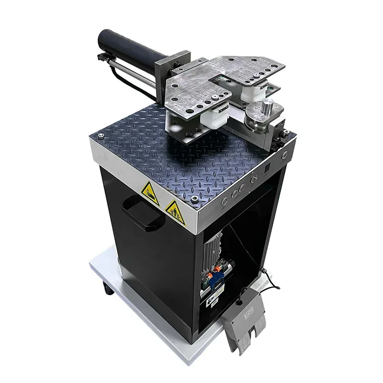
XYOON's tube cutting machine category describes cold-cutting equipment intended to feed a later deburring and fitting-preparation process. The semi-automatic tube cutting machine is the relevant product page for a fixed workshop. Its published accuracy and material range should be verified on the buyer's own tube samples before purchase.
Step 3: make the cut without crushing the tube
Use a fixture that supports the tube close enough to the cut to prevent vibration but does not flatten the wall. Confirm that the tube sits square to the blade and against the correct length stop.
For a new size or material:
- Verify blade type and condition.
- Set clamping force and feed for the tube wall and material.
- Cut one sample.
- Measure length and squareness.
- Inspect for ovality, tearing, heavy burr and heat discoloration.
- Approve the setup before releasing the batch.
Do not assume a smooth-looking face is square. Use a suitable square, fixture gauge or measurement method defined by the quality plan.
Step 4: deburr the inside and outside edges
Deburring should remove the sharp projection without turning the tube end into a large bevel. Work around the full circumference and keep the tool aligned.
Inside burrs deserve particular attention. They are easy to miss, and a loose sliver can enter the hydraulic circuit. Outside burrs and sharp edges can interfere with ring installation or damage a seal in systems that use one.
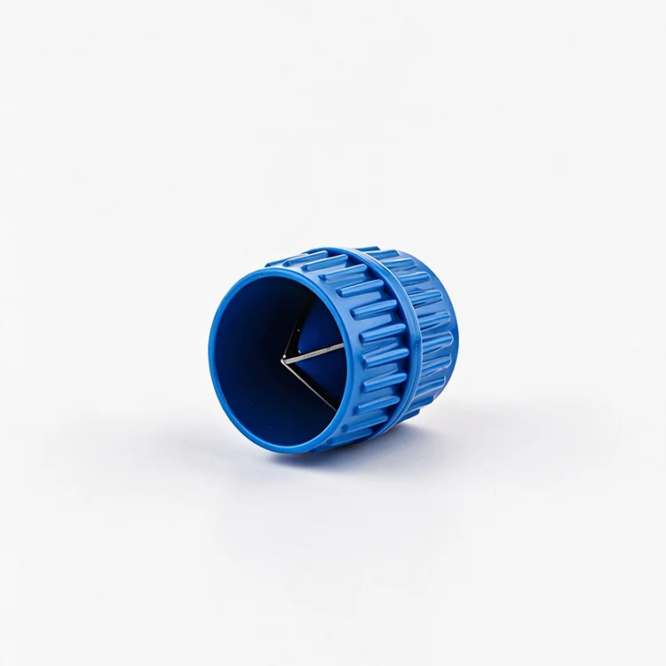
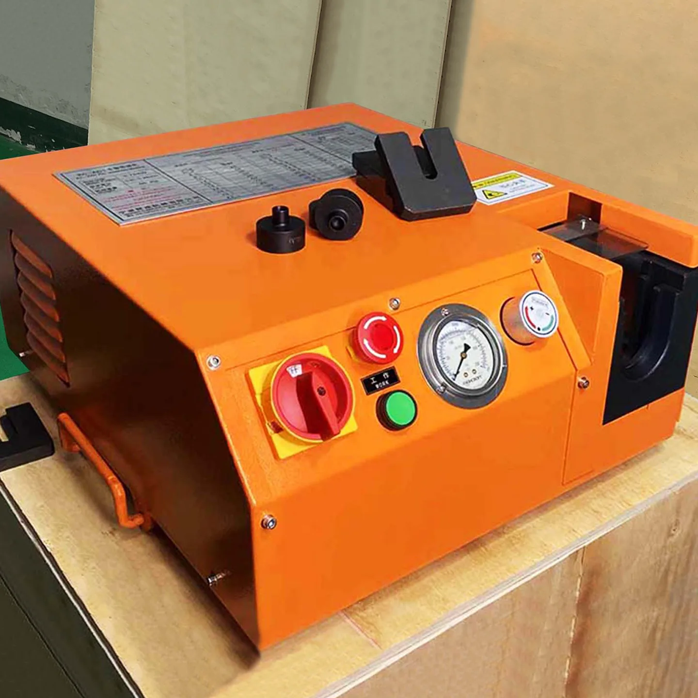
For occasional work, a correctly sized hand deburring tool may be enough. For repeated production, an electric machine can reduce variation if its guides and cutters match the tube range. XYOON lists manual and electric steel pipe deburring machines . The published electric model is specified by XYOON for 6 mm to 42 mm tube. Confirm material, wall thickness, chamfer geometry, voltage and consumables through a sample trial.
Avoid three common mistakes:
- pushing so hard that the tool chatters or cuts an uneven chamfer;
- removing more outside diameter than the fitting instructions allow;
- using the same worn cutter on different materials without checking the result.
Step 5: remove chips and protect the clean tube
Remove chips from the bore and outside surface. Use the cleaning method permitted by the site's contamination-control and safety procedures. The tube should be dry and free of loose metal, abrasive residue, oil that is not approved for the system, and lint.
Parker's EO guidance notes that chips, dirt, internal or external burrs and paint can prevent correct tube insertion. It also links dirty tube to tool wear or damage. That is a useful process-control point: cleanliness protects both the hydraulic system and the assembly tooling.
Cap or otherwise protect prepared ends if they will not move directly to the next operation. An open tube left beside a grinder is no longer a clean tube.
Step 6: inspect and record the first piece
The first-piece check should answer specific questions:
| Check | Pass condition | Typical method |
|---|---|---|
| Length | Within drawing tolerance | Caliper, rule or dedicated stop check |
| Squareness | Within fitting or drawing limit | Square, fixture gauge or measured angle |
| Outside diameter | No unacceptable collapse or flare | Micrometer at defined positions |
| Inside edge | Burr removed; bore not rolled inward | Light and visual or tactile check |
| Outside edge | Sharp edge removed without excessive chamfer | Profile gauge or approved visual standard |
| Surface | No deep scratches in the sealing or bite area | Clean, well-lit visual inspection |
| Cleanliness | No visible loose chips or residue | Visual check plus the site's cleanliness method |
Keep an approved sample or photo standard at the workstation. Words such as "smooth" and "good" are too vague when several operators share the job.
Troubleshooting tube-end defects
The face is angled
Check blade wear, guide alignment, tube support, feed pressure and whether chips are trapped against the stop. Recutting may be possible if the finished length remains within tolerance.
The tube becomes oval near the cut
Reduce or redistribute clamping force and confirm that the fixture matches the diameter. Thin-wall tube may need a dedicated support method.
A large internal burr keeps returning
Inspect blade geometry and sharpness, feed direction and cutting parameters. Do not make aggressive deburring the permanent fix for a poor cut.
The chamfer is inconsistent
Check tool centering, cutter wear and operator pressure. For batch work, a guided or powered deburring station may be easier to control than a freehand tool.
Scratches appear after deburring
Clean the fixture and guide surfaces. A trapped chip can mark every tube in a batch.
Build the workstation around flow
A practical tube-preparation cell follows the work in one direction:
- identify and measure the tube;
- cut to length;
- deburr the inside and outside edges;
- clean and inspect;
- bend or form in the sequence required by the drawing;
- pre-assemble the fitting;
- protect the finished ends.
Keep rejects and unprocessed tube physically separate from accepted pieces. Store blades, deburring cutters and assembly tools by size and material compatibility. Record changes that affect the result, including a new tube supplier, wall thickness, blade type or fitting family.
For the next stage, use the DIN 2353 cutting ring assembly and inspection guide .
What to send with a sample-trial request
An equipment supplier can give a better answer when the inquiry includes:
- tube material, outside diameter and wall thickness;
- straight, bent, round or shaped section;
- finished-length tolerance and squareness requirement;
- required edge condition or chamfer drawing;
- pieces per batch and per shift;
- available voltage, air and coolant restrictions;
- required cleanliness and sample report;
- photos of current burrs, distortion or rework;
- the fitting system used after preparation.
Send representative tube samples that include the difficult sizes. Ask for cut-face photos, measurements, deburring results, cycle method, consumable list and changeover procedure before accepting the equipment.
Need help matching a tube range, fitting series and batch requirement to the right equipment? Contact XYOON with the tube OD, wall thickness, material and expected output.