
Hydraulic tube assembly design turns system requirements and port locations into a tube that can be formed, connected and installed. A route is ready for fabrication only when the tube and fittings match the tooling, the bends leave usable straight ends, and the installation allows tools to reach the connections.
When designing a hydraulic system, selecting pumps, valves and actuators does not finish the connecting pipework. A tube can clear every nearby component in CAD and still prevent a nut from sliding into place or a wrench from turning. Those checks belong on the drawing, before the part reaches the machine.
Start with the connection ends. Confirm the ports, fittings and tool approach before optimizing the bends between them. A neat route is of little use if its final connection cannot be assembled or removed.
1. Define tube requirements within the hydraulic system design
Start with the approved operating conditions and interfaces. Hydraulic component design determines what a component must do; tube assembly design determines how the specified connections can be reached, manufactured and inspected.
Translate operating requirements into tube inputs
Record the fluid, operating pressure and temperature conditions, along with any pressure peaks or movement the system designer requires you to consider. Keep these separate from a machine's processing range. A bender's diameter range does not establish a tube assembly's pressure rating or the bore needed for the circuit.
ISO 4413 covers hydraulic system design as well as assembly, installation, maintenance and cleaning. That scope is a useful reminder to review the tube throughout its intended use, rather than only in its fitted position. [1]
| Input | Record | Why it affects the tube |
|---|---|---|
| Operating conditions | Fluid, pressure conditions, temperature and relevant duty | Establishes requirements for the tube, connection and seals |
| Tube specification | Material grade, outside diameter, wall thickness and condition | Defines the actual stock to assess with the tooling |
| End interfaces | Port type, connection series, position and axis direction | Determines mating parts and the final approach |
| Installation envelope | Fixed obstacles, moving parts, heat sources and support locations | Constrains the route and access |
| Acceptance requirements | Drawing revision, dimensions, tolerances and inspection method | Defines what a conforming first part must demonstrate |
Define the installation envelope, not just the finished outline
Include the path used to insert and remove the tube, the space needed to assemble its ends, and nearby components' movement. For a custom hydraulic system, confirm which interfaces are fixed before optimizing the route around them. A later port change can invalidate otherwise correct bends.
2. Match the tube, fittings and fabrication tools
Treat the tube, connection and tooling as one combination. Record the material and wall thickness beside the outside diameter, then identify the fitting series and the tools required for that connection.
Different connection systems need different preparation
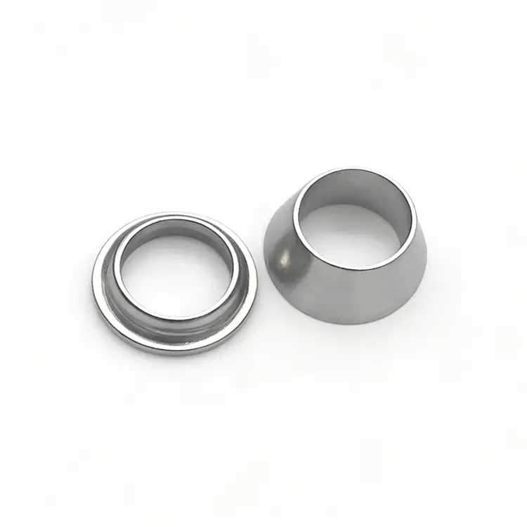
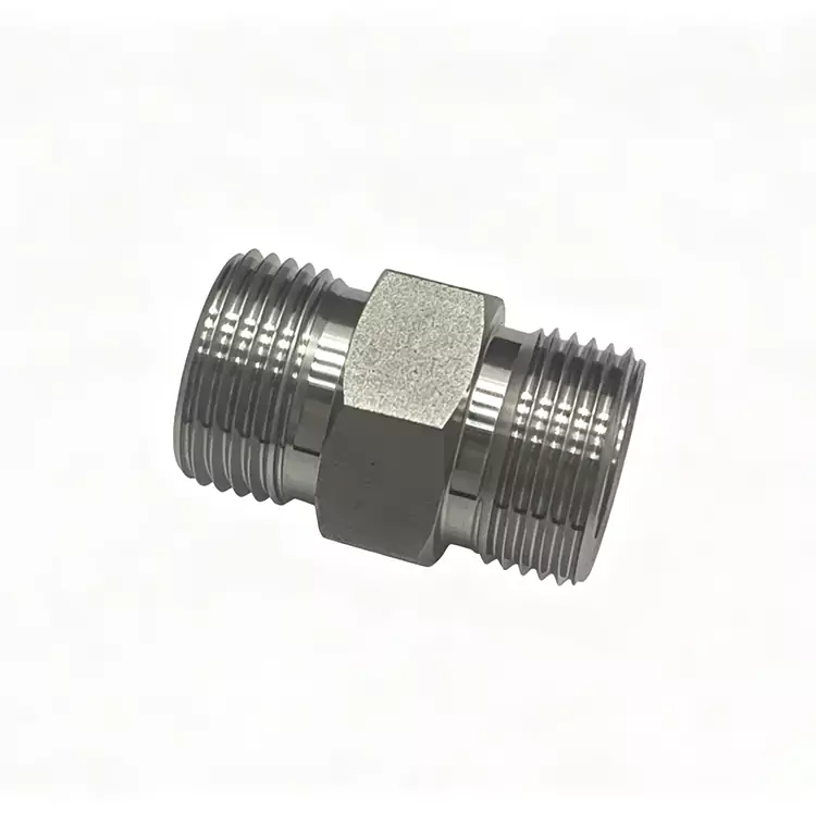
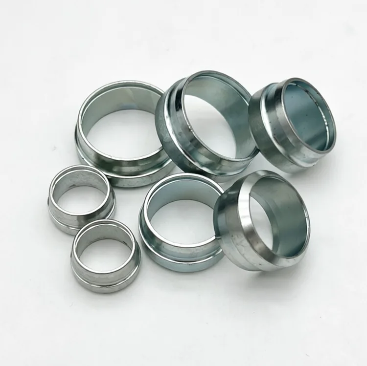
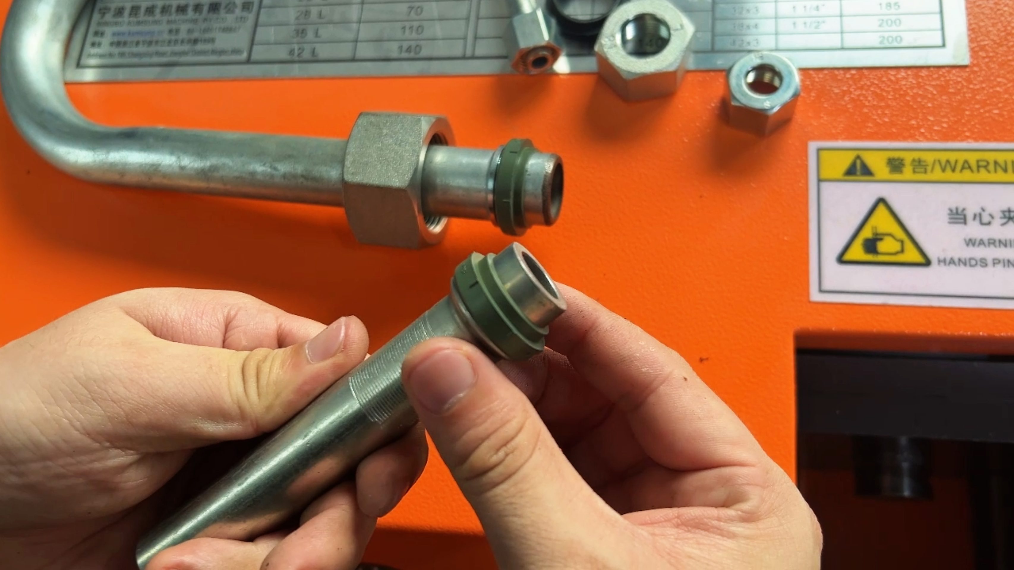
Our rigid pipe hydraulic fittings include 24° bite-type, 37° flare and weldable configurations. These are different connection methods, not alternative names for the same tube end.
| Connection | Preparation to plan | Drawing review question |
|---|---|---|
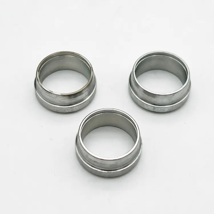
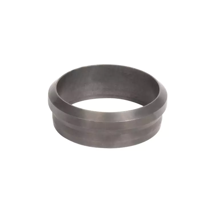
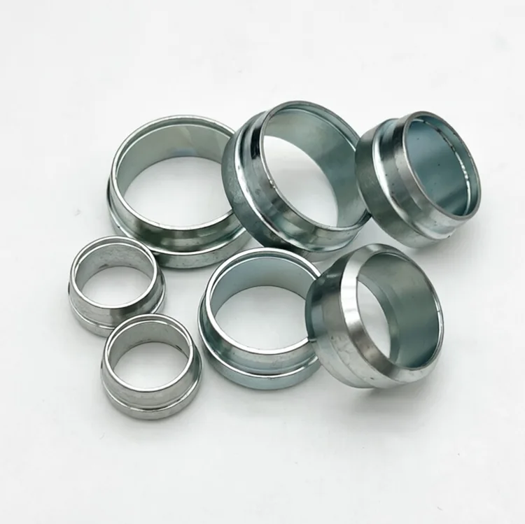
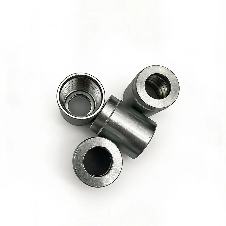
| 24° cutting ring | Matched tube, nut, ring and preassembly tool; inspection under the specific fitting instructions | Can the parts be loaded and the correct tool reach the straight tube end? |
| 37° flare | The specified flare geometry, matching tooling and associated hardware | Can the end enter the flaring tool after the planned bends? |
| Weldable end | The specified weld preparation, joining procedure and subsequent cleaning/inspection | Is there access for the approved joining and inspection process? |
ISO 8434-1:2018 addresses 24° cone connectors, including cutting ring and DKO designs. ISO 8434-2:2007 addresses 37° flared connectors. Identify the applicable connection specification and edition; a shared tube diameter does not establish interchangeability between these systems. [2] [3]
A diameter range is a starting filter
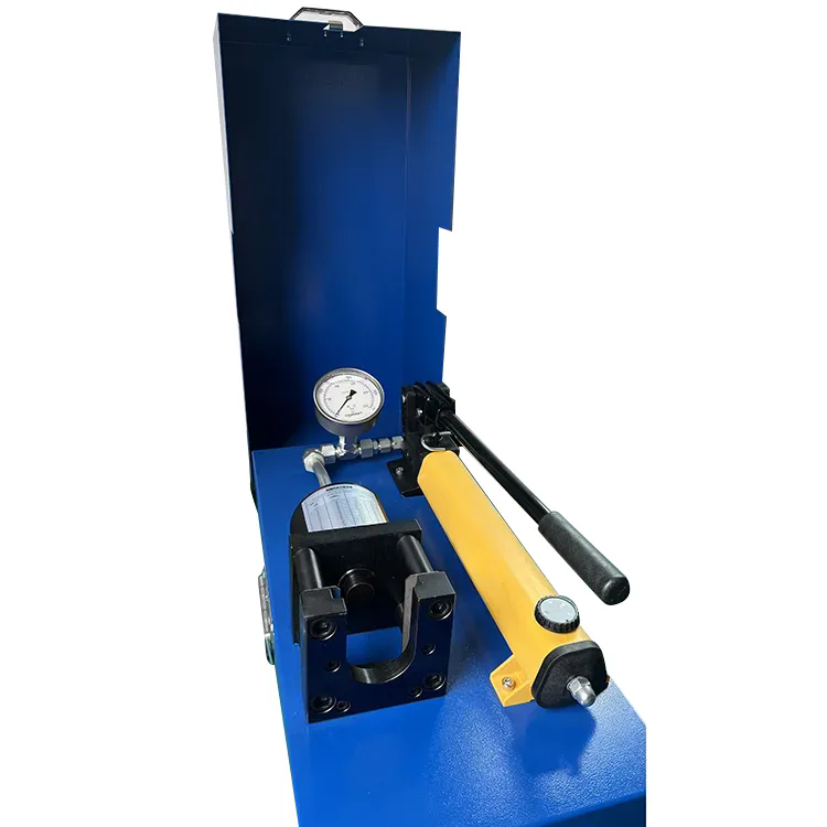
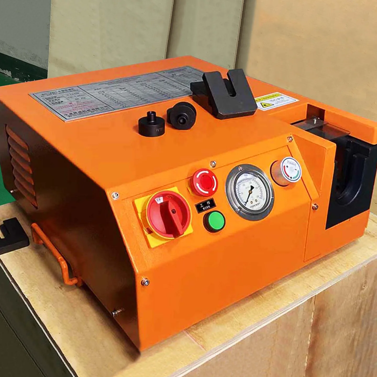
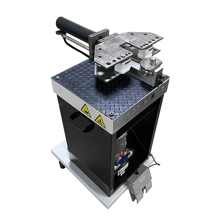
The XYOON KC-K01 memory pipe bending machine and KC-A01 electric cutting ring pre-assembly flaring machine cover a 6 to 42 mm tube diameter range. That shared range is useful for shortlisting equipment. It does not confirm the required bend radius, wall thickness, connection tooling or access for a particular finished part.
Before release, pair each tube specification with its bend die and connection tool. Include tool identities in the part record so that a change of die or fitting series triggers a review rather than an unnoticed substitution.


3. Plan tube routing for compact and mobile equipment
Review the route in the order the machine will be assembled and serviced. The final tube outline is only one part of that check; the insertion path, surrounding movement and tool access also need space.
Separate fixed routes from moving interfaces
For hydraulic systems for mobile equipment, identify which components move relative to each other. Do not treat a rigid tube spanning such an interface as a routine fixed connection. Resolve the movement with the system designer and the applicable connection arrangement.
Mark mounting points and moving-part envelopes on the same installation model. Keep the proposed route clear of those envelopes throughout the required motion. Review support locations with the installation design; a generic clamp spacing copied from a different tube or duty is not a substitute.
Check access even when the system is small
A small hydraulic system can leave very little room around a valve block. Check how the tube enters, where the wrench approaches and whether a neighboring component must be removed first. Record an unavoidable removal dependency in the assembly instructions rather than leaving the installer to discover it.
Use a bend when the available tooling can produce the route and retain usable ends. Consider an elbow or separable section when it resolves a defined access problem. Compare the complete arrangement, including additional connections and the assembly sequence, instead of assuming the fewest fittings always gives the most practical result.
4. Choose bend radii that match the tube and tooling
Specify the centerline bend radius and check it against the actual tube and die. A radius that fits the installation is not automatically a radius the selected setup can form acceptably.
A larger radius can consume the connection straight
Hold the tube end and the theoretical corner fixed, then increase the radius. The bend starts earlier along the incoming leg, leaving less straight tube at the connection. That geometric trade-off is easy to miss when reviewing only the space around the curved section.
For a simple circular bend with direction change θ between 0° and 180°, the tangent setback is R × tan(θ/2). If A is measured from the tube end plane to the theoretical corner along the incoming centerline:
For θ = 90°: L = A − R
For a geometry example, assume A = 65 mm and a 90° bend. A 30 mm centerline radius leaves 35 mm straight. Increasing the radius to 45 mm leaves 20 mm: 15 mm less connection straight, even though the end and theoretical corner have not moved.
These assumed dimensions illustrate geometry, not an approved tube specification. Compare the resulting straight with the exact fitting and tooling requirements. The calculation does not establish bendability, an allowable wall thickness, springback compensation or the cut length of the blank.
Confirm the formed section as well as the radius
Inspect the trial bend against the drawing's requirements for angle, cross-section and surface condition. If the selected radius or tube changes, revisit the connection ends and the remaining bend sequence. Do not approve the change from a radius number alone.
5. Reserve straight ends and fitting tool clearance
Start a fabrication review at the two ends of the tube. Check that the hardware can be loaded and that the preassembly tool and final wrench can approach. Then examine the bends between those ends.
If the last bend sits close to a connection, changing the angle alone may not solve the problem. Check the remaining straight, the grip location and the operation order. Compare moving the bend, changing the connection arrangement or dividing the assembly. Do not use the fitting nut to pull a misaligned tube into position.
Give each operation its own space check
| Operation | Check | Use as the basis |
|---|---|---|
| Load hardware | Can the nut, ring or specified sleeve reach its position in the planned sequence? | Actual component geometry and fitting instructions |
| Hold for bending | Is enough suitable straight tube available at the required grip location? | Selected bend tooling and workholding |
| Prepare the connection | Can the end enter the tool, complete its operation and withdraw? | Exact preassembly or flaring setup |
| Complete installation | Can the required wrench engage and move with surrounding parts installed? | Specified assembly method and installation model |
| Remove for service | Can the connection separate and the tube leave its installed position? | Maintenance sequence and removal path |
Do not turn several clearances into one guessed dimension
Some requirements act along the tube; others require radial access or a tool sweep. Adding them all into a single straight-length allowance can hide the actual interference. Record both the required straight length and the relevant approach envelope.
Obtain dimensional requirements from the matching fitting and tool information. If access still needs confirmation, use the actual tooling and a representative part before releasing the drawing. Nominal outside diameter alone is not enough to specify a universal minimum straight.
6. Define datums, rotation and bend sequence
A multi-bend tube needs more than a list of angles. Define the reference end, the locations of bends and the rotation between bend planes. Two parts can have the same bend angles yet finish with different end positions or directions.
State how the tube is viewed
Mark datum A and the viewing direction used to describe rotation. Identify whether a distance refers to a tangent, theoretical corner or another drawing feature. A bare list of numbers leaves too much room for different interpretations.
Review the next bend before making the current one
Check whether an earlier bend blocks the next grip location, the workpiece's rotation or tool withdrawal. A sequence that works on an unbent blank may become inaccessible once a leg has been formed.
The KC-K01 uses angle memory and compensation settings. Those features help manage repeated bend settings, but they do not define the tube's axial locations or rotation references. Keep the drawing revision, tooling and relevant setup information together.

7. Review fabrication before releasing the drawing
Walk the proposed part through its operation sequence. Check what must already be fitted, which straight portions remain available and how the part leaves each tool.
Separate blank preparation from finished geometry
The cut length of a blank and the finished tube's end-to-end dimensions describe different things. Define the blank through the approved fabrication method and verify the finished geometry against the drawing. The straight-end calculation above is not a developed-length calculation.
Plan cutting, deburring and cleaning as controlled handoffs. Our hydraulic tube cutting and deburring guide covers tube-end preparation in more detail. Protect prepared ends during later handling rather than assuming one cleaning step settles the whole route.
Decide when hardware and connection preparation belong
- Check whether the specified nut or sleeve can still slide into place after the bends.
- Check whether connection preparation before bending would obstruct the bending tool or damage a prepared end.
- Check whether bending first leaves enough room for the connection tool and its withdrawal.
- Record the chosen order for the part family, together with inspection and protection requirements.
There is no useful universal instruction to bend every part first or preassemble every connection first. Approve the sequence that works with the specific geometry, tooling and fitting instructions.
8. Resolve drawing conflicts before fabrication
Use the drawing review to identify a specific conflict and the evidence needed to close it. An instruction such as "allow sufficient clearance" is incomplete until the affected operation and required space are defined.
| Conflict | Check first | Review these changes |
|---|---|---|
| The last bend crowds the fitting | Tangent-to-end straight and tool approach | Bend position, end configuration or operation order |
| No matching die for the radius | Tool list and actual material/wall combination | Radius or a suitable validated tooling arrangement |
| The tube fits but the wrench does not | Tool engagement and movement with neighboring parts installed | Connection position, assembly order or separable section |
| A formed leg blocks the next operation | Remaining grip, rotation and withdrawal paths | Bend sequence, workholding or part geometry |
| Angles pass but ports do not align | Reference end, bend locations and plane rotation | Drawing definitions and setup translation |
| The end enters a tool but the connection is wrong | Exact fitting series and tool identity | Correct component/tool pairing before further parts |
| Prepared ends become contaminated | Handling after end preparation | Protection and the next operation's handoff |
| A sample fits but the setup cannot be repeated | Material, tooling, settings and revision records | Controlled setup and inspection instructions |
Choose a change that closes the whole conflict. Moving a bend to free the wrench is not a complete solution if it then removes the machine's grip length.
9. Validate the first tube in its installation context
Keep geometric inspection, connection preparation and installed fit as separate acceptance decisions. Passing a fixture confirms only what that fixture was designed to check.
Define what each check demonstrates
| Review | Evidence to retain | What it does not establish by itself |
|---|---|---|
| Tube geometry | Measured dimensions and orientation against the drawing revision | Tool access or connection performance |
| Connection preparation | Inspection under the exact fitting/tool instructions | Clearance in the installed machine |
| Installation and service | Port alignment, insertion, wrench access and removal check | Hydraulic pressure or duty-cycle performance |
| Required functional or qualification checks | Results under the approved project/component test procedure | Approval of untested configurations or changed materials |
Separate connection qualification from an installation trial
ISO 19879:2021 defines test methods for metallic hydraulic connections. Its scope distinguishes test methods from the applicable component standard's test selection and performance criteria. A dimensional inspection or successful trial installation is not a substitute for those requirements. [4]
Set the necessary pressure and functional checks through the approved project procedure, with the responsible personnel and safeguards. Do not assign an arbitrary proof pressure or cycle count from a general routing guide.
Before approving repeated production, retain the accepted drawing revision and the matching material, tooling and setup records. Reassess the affected checks when any of those inputs changes.
10. Prepare the tube drawing and tooling information
A useful drawing package connects the finished shape to the method used to make and install it. Include the revised 2D/3D drawing, material and wall thickness, complete connection identification, datums and acceptance requirements. Add the available machine/tool information and any installation restrictions that cannot be understood from the part drawing alone.
How to review a hydraulic tube drawing before release
- Confirm the inputs. Match the drawing revision to the required tube specification, operating conditions, ports and connection parts. Resolve conflicting identifiers before assessing the route.
- Check the geometry against the tooling. Identify the bend radii, straight ends, datums and rotation references. Compare them with the actual bend and connection tools, including grip requirements.
- Walk through fabrication. Check hardware loading, bend order, end preparation and tool withdrawal in sequence. Record any restriction that changes the order of operations.
- Review installation and removal. Check insertion, port alignment, wrench movement and the service removal path in the intended installation. Include the required movement envelope for the application.
- Close the acceptance record. Record the results of the specified first-part and installation checks, close drawing changes, and associate the accepted setup with the released revision.
For XYOON tube processing equipment and matching fittings, send the drawing, tube specification, connection details and the operation that limits your current setup to sales@xyoon.com. You can also use our contact page to discuss the required equipment and tooling.
Release the route when the connection ends, fabrication sequence and installed access have all been checked. If one remains unresolved, changing the centerline alone does not finish the design.
Frequently asked questions
How close can a bend be to a hydraulic fitting?
Use the straight-end and access requirements of the exact fitting and tools. Measure the straight to the bend tangent, then check hardware loading, workholding, connection preparation and final wrench access separately. Tube outside diameter alone does not define a universal minimum distance.
Does a smaller hydraulic system always need a smaller bend radius?
No. A compact installation does not change the selected tube's material, wall thickness or tooling requirements. Resolve the space restriction by comparing feasible radii, connection positions and routing arrangements. A tighter radius needs confirmation for that tube and setup.
Does the same tube diameter allow the same tooling?
Not automatically. Check material, wall thickness, bend radius, connection system and tool compatibility. Bending tools and connection preparation tools perform different jobs; sharing a nominal diameter does not make their setups interchangeable.
Why can a tube pass a fixture check but still be difficult to install?
The fixture may check geometry without representing neighboring components, insertion direction or wrench movement. Verify installed port alignment and the actual assembly and removal paths separately. Treat fixture acceptance as evidence for its defined checks, not as proof of complete installation access.
Sources
- ISO 4413:2010: hydraulic system rules and safety requirements. Scope includes design, assembly, installation, maintenance and cleaning.
- ISO 8434-1:2018: 24° cone connectors. Scope identifies cutting ring and DKO connector arrangements.
- ISO 8434-2:2007: 37° flared connectors. Use the applicable edition specified for the connection; ISO lists a revision in development.
- ISO 19879:2021: test methods for hydraulic connections. Test selection and performance criteria depend on the applicable component standard.