
Article Summary:
A clean visual inspection and the correct cone gauge reveal different kinds of assembly-tool damage. This guide explains how to check cutting ring assembly studs, set evidence-based inspection intervals and keep questionable tools out of production.
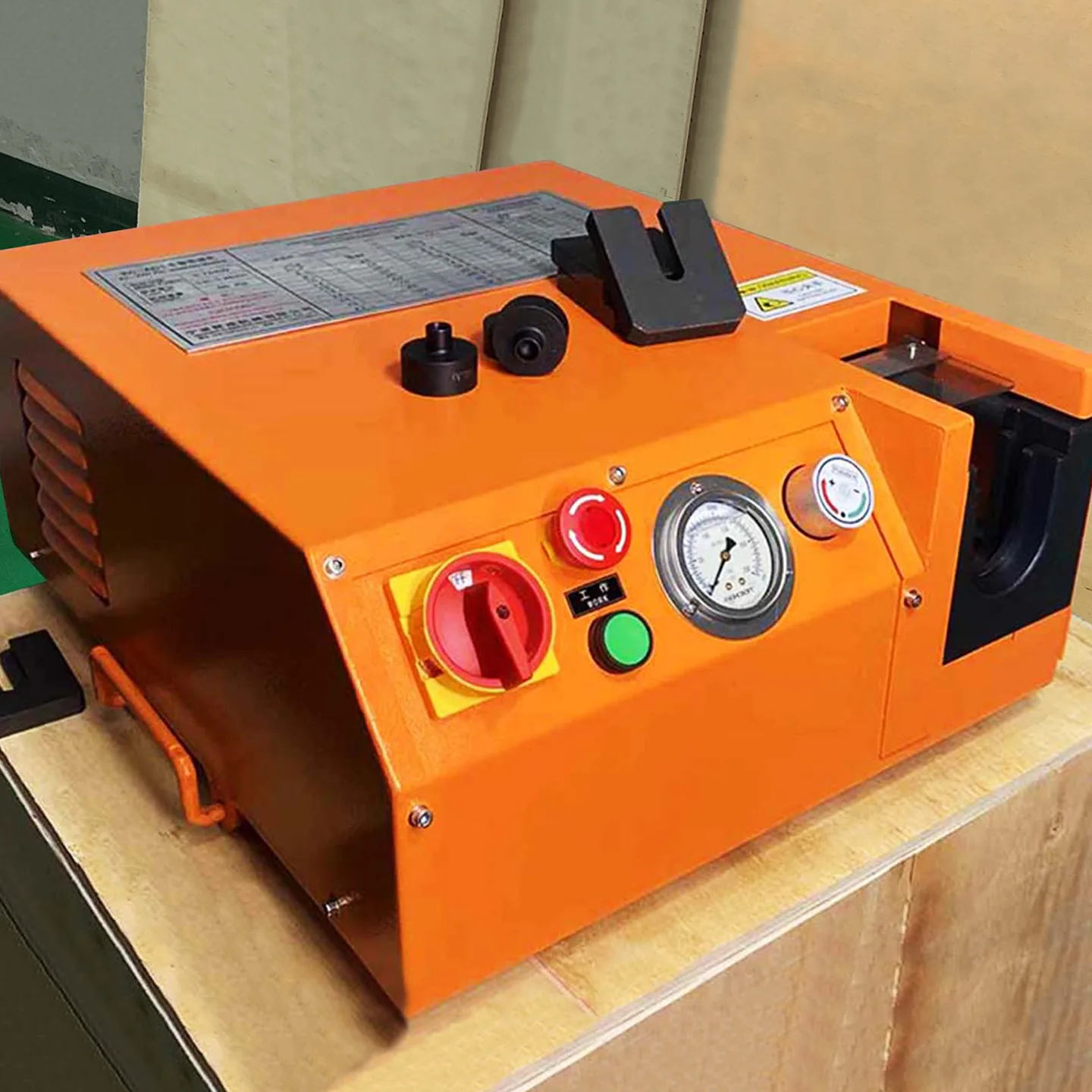
Clean the assembly stud, inspect the 24 degree cone under good light, then check its dimensional accuracy with the correct cone gauge for the tool manufacturer, tube size and series. Remove the tool from service if it has cracks, scoring, material erosion, deformation or an out-of-limit gauge result.
Do not wait for a leaking connection to trigger the inspection. Worn tooling can change the ring position and bite across an entire batch before the defect becomes obvious.
What counts as an assembly tool?
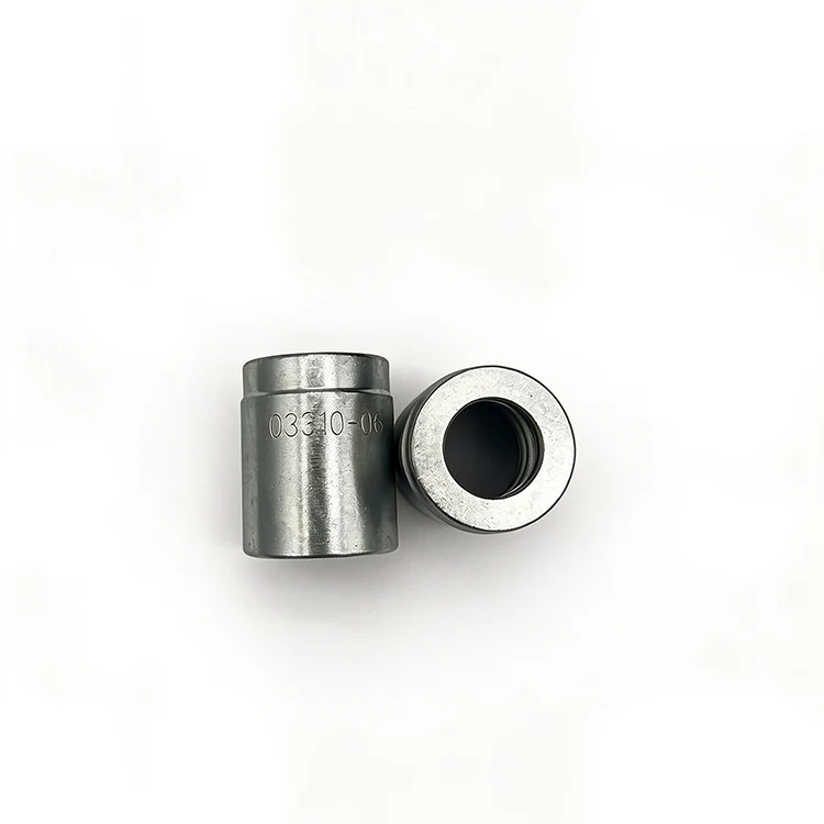
In a cutting ring process, the assembly tool may be called an assembly stud, pre-assembly connector, pre-assembly socket, presetting body, assembly cone or mandrel. The names vary, but the critical feature is the internal cone that guides and loads the cutting ring.
The surrounding support plate, tube stop, holder and machine interface also affect alignment. A good cone installed with the wrong support plate or series can still produce a bad result.
Record the complete tool identity:
- tool manufacturer and part number;
- tube outside diameter;
- LL, L, S or other series;
- compatible cutting ring family and material;
- machine or manual holder used;
- date placed in service and inspection status.
Why cone wear changes the assembly result
The cone controls how the ring advances and where force is applied. Wear, expansion or embedded debris can change that geometry. The result may be shallow bite, excessive ring travel, uneven material build-up, scoring or deformation.
STAUFF's current manual for its portable pre-assembly device states that worn or expanded assembly studs influence the quality of the pressed connection. Parker likewise warns in its EOMAT PRO documentation that damaged, worn or unsuitable tooling can lead to fitting failure or machine damage.
Tool wear is not the only possible cause of a defect. Tube preparation, seating, component mismatch and incorrect settings can create similar symptoms. Use the cutting ring assembly defect guide to separate these causes.
A practical inspection sequence
1. Stop and identify the tool
Remove the tool using the machine manufacturer's safe procedure. Confirm its size and series before inspection. Keep L and S tooling separate even when the tube OD is the same.
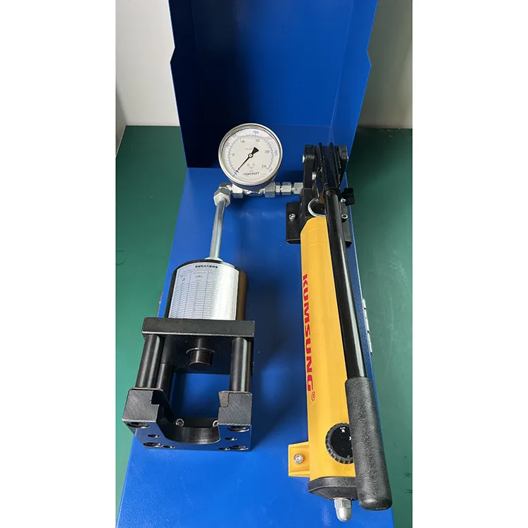
Do not inspect a tool while the machine can move. Isolate energy and follow the equipment manual for access to the assembly area.
2. Clean without damaging the surface
Remove oil, chips and dirt so the cone surface is visible. Use the cleaning method and materials approved by the tool manufacturer. Do not polish the cone, use an abrasive wheel or alter the surface to make a damaged tool pass.
Parker instructs users to clean the cone surface before checking its MOK-PRO tools. STAUFF also links regular cleaning, lubrication and protected storage with longer tool life.
3. Inspect under controlled light
Rotate the tool and change the light angle. Check the full cone, stop area and entrance for:
- cracks or chipped edges;
- scratches, grooves and notches;
- transferred tube or ring material;
- corrosion or pitting;
- uneven polished bands;
- impact marks and deformation;
- dirt packed into the stop or contact surface.
A defect that catches a fingernail is not a measurement, but it is a reason to stop and follow the replacement rule. Parker states that tools with visible wear or cracks must be replaced even when a cone-template check appears acceptable.
4. Check geometry with the approved cone gauge
Use the gauge specified for the assembly tool. Verify the gauge part number, tube size and series. Clean both contact surfaces and seat the gauge exactly as its instructions require. Do not force, rock or rotate it in a way the manufacturer does not permit.
For Parker MOK-PRO tools, the published check uses a KONU template. Parker states that the rear of its template should project slightly above the top face of the cone or may be flush. That acceptance description belongs to Parker's tool and gauge. A STAUFF FI-KOL gauge or VOSS cone gauge may use a different reading method.
5. Record the result and disposition
Mark the tool as accepted, quarantined or scrapped. Record the gauge used, inspector, date, cycle count or batch count, visual findings and replacement decision. If the tool fails, identify every part produced since the last accepted check and apply the site's containment procedure.
Visual inspection and gauge inspection answer different questions
| Check | What it can reveal | What it cannot prove |
|---|---|---|
| Cleaning and visual inspection | Cracks, scoring, corrosion, chips, material transfer and obvious deformation | Dimensional accuracy of a surface that still looks smooth |
| Cone gauge or template | Whether the specified cone geometry remains within that gauge's acceptance method | That the completed cutting ring assembly is correct in every respect |
| First-piece assembly inspection | Ring position, material build-up, fit and unwanted tube deformation | The remaining life of the assembly tool |
| Machine process monitoring | Pressure or position drift when the machine has suitable controls | Surface condition that the sensor does not measure |
Use all applicable checks. VOSS explicitly states that its inspection gauge for a pre-assembled tube does not eliminate the visual check of the material pushed up by the cutting edge. In the same way, a cone gauge for tooling does not approve the finished tube assembly.
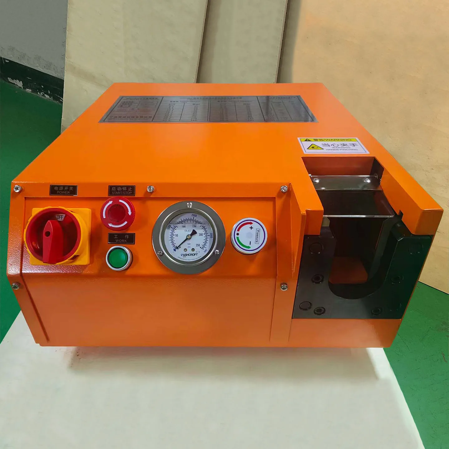
How often should assembly tools be checked?
Follow the current instructions for the exact tool. There is no reliable universal service life in cycles because material, size, lubrication, contamination, storage and assembly load all affect wear.
Several current manufacturer instructions use a 50-assembly maximum interval for specific conventional tools:
- STAUFF's cone gauge page cites a wear check after 50 assembly processes for the relevant assembly studs under DIN 3859-2.
- Parker's EOMAT PRO guide says its MOK-PRO tools must be checked regularly, at least after 50 assemblies.
- VOSS's cone gauge page says the basic version of its pre-assembly nipples requires visual and gauge-accuracy checks at least every 50 pre-assemblies.
These are manufacturer and product-specific requirements. VOSS also publishes a high-performance pre-assembly connector with a different monitoring approach. Do not transfer the 50-cycle interval to every tool, and do not lengthen a stated interval because a tool still looks good.
Add an immediate check after an abnormal event, such as:
- a jam, impact or incorrect tool installation;
- an assembly cycle with the wrong tube or ring;
- visible chips or contamination in the cone;
- an unexpected machine pressure or position warning;
- a sudden change in first-piece inspection results;
- corrosion after storage or transport.
These event-based checks are a conservative control recommendation. The owner should approve them in the workshop procedure.
What a cone gauge result means
A cone gauge compares the tool with a defined geometry. It does not measure "percent wear" or predict a remaining number of cycles unless the gauge manufacturer specifically provides that method.
Use these rules:
- Match the gauge to the tool brand and part number.
- Confirm the gauge itself is clean, undamaged and within its calibration or control status.
- Follow the published seating and reading method.
- Reject or quarantine the tool when the result is outside the stated limit.
- Reject visible cracks or serious damage even if the dimensional check passes.
Never grind, lap or re-machine a worn cone unless the tool manufacturer provides an approved repair and requalification process.
Warning signs in production data
Tool wear can appear as gradual drift rather than a single dramatic failure. Review trends such as:
- increasing machine travel at similar pressure;
- repeated pressure or position warnings;
- material build-up moving around the tube circumference;
- more rings that remain loose after pre-assembly;
- rising tube-end deformation or surface scoring;
- defects that disappear after a tool change but return with the old tool.
These signs justify inspection, but they do not prove wear by themselves. Compare the last accepted part, first rejected part, tool gauge result and machine record before assigning the cause.
STAUFF describes combined pressure and position control as a way its workshop final-assembly machine can detect tool wear before it affects the result. Machines without that function need a manual inspection plan. Machines with it still need the visual and dimensional checks specified by the manufacturer.
Cleaning, lubrication and storage
Preventive care is cheaper than sorting a suspect batch, but the lubricant and interval must come from the tool instructions.
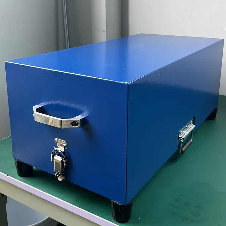
| Control | Practical requirement |
|---|---|
| Cleaning | Remove chips and residue before they score the cone or prevent full tube seating |
| Lubrication | Apply only the approved oil or lubricant in the stated amount and location |
| Storage | Protect tools from impact, contamination, moisture and corrosion |
| Identification | Store by manufacturer, size and series with readable labels |
| Gauge care | Treat cone gauges as measuring devices, not general hand tools |
| Records | Track inspections, abnormal events, replacements and affected batches |
STAUFF's SPR-PRC-H manual instructs users to oil its assembly stud lightly at regular intervals with the supplied assembly oil. Parker similarly tells users to keep its tools clean and lubricated. Those instructions apply to their respective products; use the XYOON-approved lubricant for XYOON tooling.
What to request from XYOON
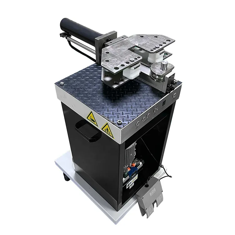
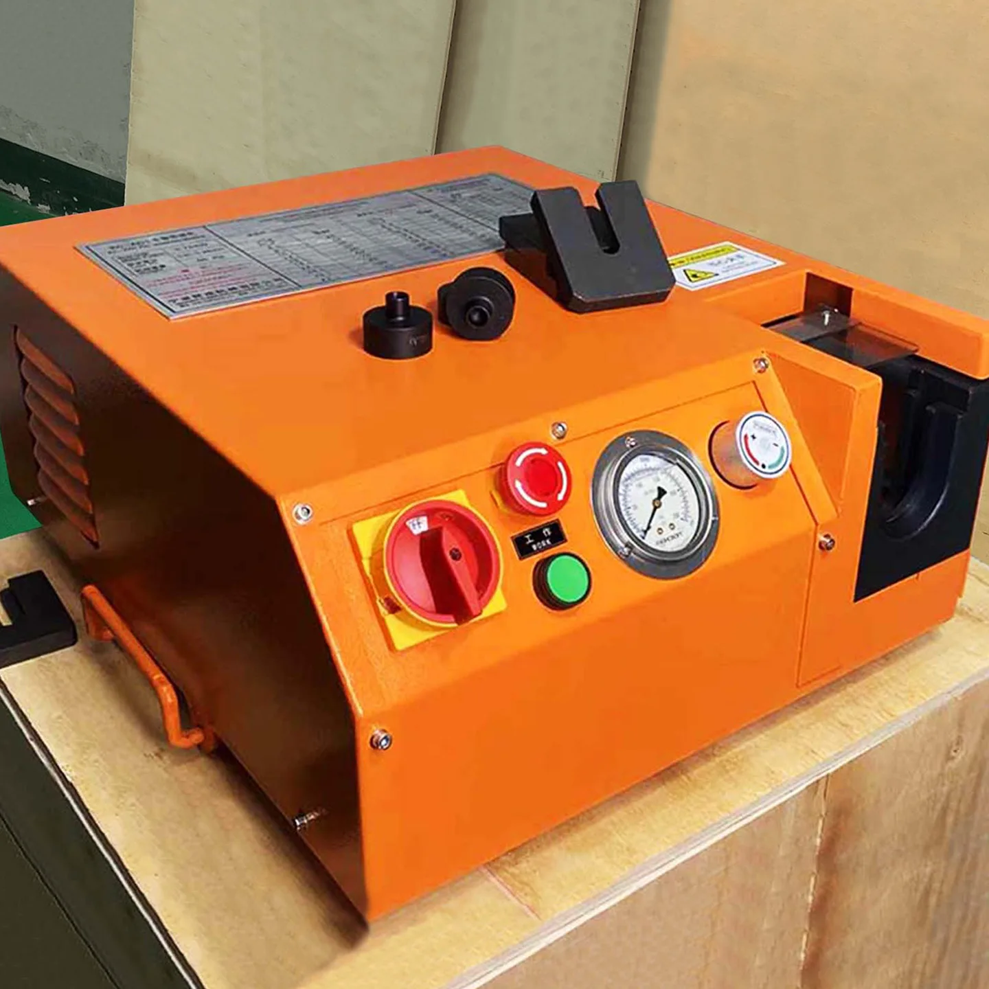
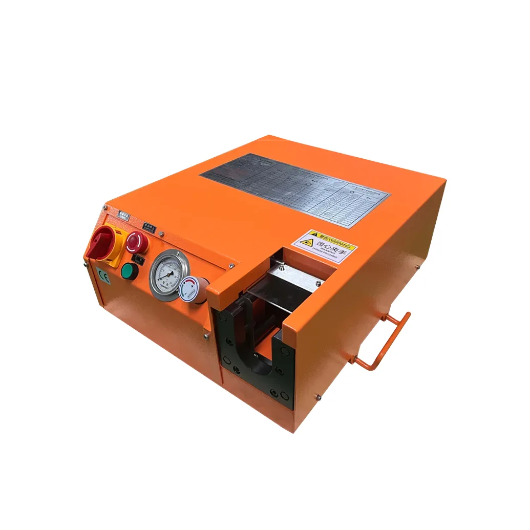
XYOON publishes manual and electric products in its cutting ring pre-assembly machine range. The public pages show replaceable tooling, but they do not currently provide a controlled cone-gauge procedure or part-specific discard limits.
Before production, request:
- an assembly stud list by fitting brand, tube OD and series;
- the matching inspection gauge and instructions;
- visual rejection examples;
- maximum inspection interval and event-based check rules;
- approved cleaning, lubrication and storage method;
- replacement part numbers and traceability markings;
- a procedure for containing parts made with a failed tool;
- a first-piece acceptance sample for every approved setup.
If the machine processes several fitting brands, do not assume one cone gauge or wear limit applies to all tooling. Use the XYOON inquiry page to send the machine model, tool markings, fitting system and photos of the cone.
A usable tool-inspection record
The record can fit on one page or in a simple digital form:
| Field | Example entry |
|---|---|
| Machine | Model and serial number |
| Assembly tool | Manufacturer, part number, OD and series |
| Fitting system | Brand, ring family and material |
| Inspection trigger | Scheduled count, changeover, warning or defect |
| Visual result | Accept, damage noted or contamination removed |
| Gauge | Part number and control status |
| Gauge result | Accept or reject according to the gauge instructions |
| Disposition | Return to service, quarantine or replace |
| Product containment | Batch or serial range reviewed |
| Approval | Inspector, date and reviewer |
This record creates a link between tooling condition and product quality. It also prevents a rejected stud from returning to the workstation without authorization.
Need help matching a tube range, fitting series and batch requirement to the right equipment? Contact XYOON with the tube OD, wall thickness, material and expected output.